The purely analogue FM radio Beolit 505 from the mid 70ties lacks the newer DAB+ option. This project will be about upgrading the Beolit 505 with a DAB+/FM radio unit. The ideas about integrating old analogue electronics with newer electronics is “reused” from the “Rotary phone with integrated 4G phone” project in order to upgrade the Beolit 505 with a DAB+/FM radio unit.:

The Karcher 2405 DAB+/FM radio is used because it is able to store 10 programmable DAB+ channels and 10 programmable FM stations, but most important: the radio and the man-machine interface has the right size to fit into the Beolit. The Beolit 505 schematic can be found here: https://beo.zone/en/beolit-505/. The block schematic shows the main parts for the Beolit/DAB+ integration: Beolit 505 interface considerations.

The microcontroller uses the following input signals from the Beolit operator panel: the loudspeaker volume slider, the tuning slider and -AFC/AFC switch. The volume slider works with the original 47Kohm log. potentiometer. The tuning slider originally works with a variable capacitor., this one is replaced by a 10KOhm linear pot.meter. The microcontroller determine the slider positions from the voltage value read from the potentiometers. The original -AFC/AFC switch will be used to select the DAB+/FM option. The treble level switch will be used to switch in a coil in series with the loudspeaker.
The Beolit top-, front- and back covers are easily removed and the “inner life” of the radio back side ( with removed lits for the FM tuner and the mains power supply ) looks like this:

The middle pin of the volume slider pot.meter is not used in the project. The small VHF stage PCB at housing on the rightmost side is removed and replaced by the microcontroller PCB. The variable capacitor in the VHF stage housing is replaced by a potentiometer to read the voltage related to the tuning slider position. The PCB between the loudspeaker and the VHF stage housing holds the intermediate frequency amplifier , the FM detector and the loudspeaker amplifier. This PCB is replaced by the DAB+ radio PCB with the operator panel. The Beolit loudspeaker stays in place and mains supply on the leftmost side is modifed to provide 1.8 V DC for the microcontroller and 5 V DC for Karcher radio.
Karcher 2405 interface considerations.

The Karcher main parts looks like this:

The front cover only holds the loudspeaker in a separate area, so this part is cutted out, because the Beolit loudspeaker is used:

Just to check the proportions Beolit rear plus the shrinked Karcher front cover with the PCBs:

The idea is remove the Beolit back cover and use the shrinked Karcher operator panel in cases when the DAB+/FM channels are changed and stored. The microcontroller saves the channel choice at the same time.
The microswitches on the Karcher PCBs has ground on one side and a 1.8 V DC signal on the second side. When pushing a microswitch, the 1.8 V DC signal is grounded at a current less than 10 uA. The microcontroller has common ground with Karcher PCBs and has a 1.8 V DC power supply to fit the microswitch signal levels. Thus for the microcontroller to emulate a microswitch push , a digital output pin just need to go from tristate to active low for a specific time.
Before disassembling the Beolit, the complete microcontroller set-up can made and tested with the Karcher PCBs . A small Attiny861A testboard was made to test the software needed to emulate the DAB radio microswitches with simulated inputs from the Beolit operator panel using external switches and potentiometers:

So far, the schematic for the first test looks like this:

Notes:
Be sure to use low ESR capacitors for C1 and C2 to keep the TLV1117 regulation noise level low.
The A/D conversion with the 1.8 V DC supply works in my case only with the internal 1.1 V reference.
To keep the analogue input noise level as low as possible , no digital output takes place during an A/D conversion.
The wiring of GND and centerpin of the volume potentiometer to the A/D input circuit is made as twisted pair, see image below.
The right side of the image shows the a break-out version of Attiny861A board in the former Beolit VHF stage housing. The variable tuning capacitor was removed and a small 10 K potentiometer is connected to the tuning mechanism via a 6 mm rigid shaft coupling. The potentiometer is going to be connected to an A/D input for the microcontroller to decide when to restore/store a DAB or FM channel selection.
 A small video shows the volume test: Volume-test .
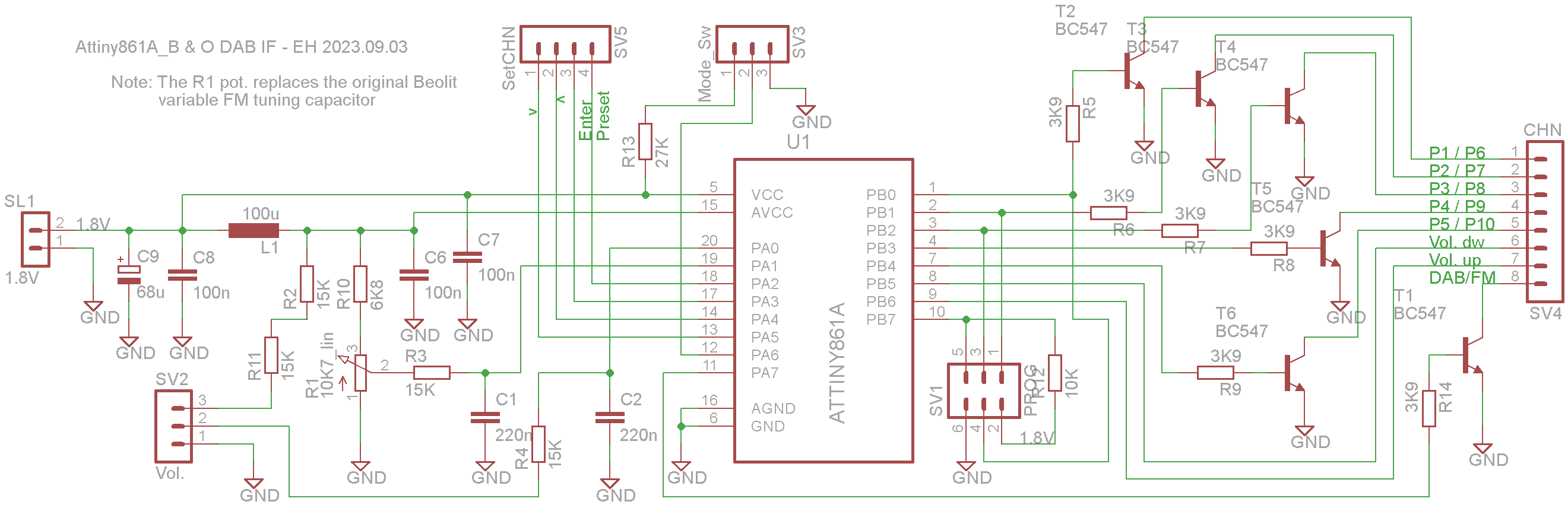
So far the volume and tuning HW and SW interfaces work ok. The channel store state machine for microcontroller is pending, but the port interrupt routine for programming buttons Preset, < , > and Enter is working. The HW schematic looks like this:
Two simple power regulators have been made, one with input from the Beolit supply to provide 5 V DC to the Karcher radio. The second regulator with input from 5 V DC supply to provide 1.8 V DC to the microcontroller, which is placed on rear side of the Karcher radio PCB:
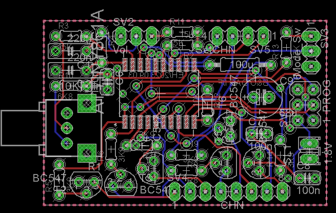
A PCB was made to hold the tuning pot.meter and that fits into the B&O VHF stage cage:
Test setup using the PCB with connections the Karcher DAB radio and the B & O radio chassis:

The Karcher radio is in place. I reused the original Beolit power supply, but increased the output voltage to 8 V DC to provide input power for a 5 V DC supply with a LM7805 regulator. The 5 V DC output from regulator ( to be seen left to the loudspeaker on the left image ) powers the Karcher radio. The Karcher can also be powered by 4 pcs 1,5 V alkaline batteries. The Beolit battery “tube” cartridge holds 5 pcs 1,5 V alkaline batteries, so a “dummy battery” with an iron screw inside has been made, it’s the white item at right image. The Karcher radio earphone output is feed to the Beolit 5 pin “Tape output” DIN connector. An adapter has been made to feed the Karcher radio earphone output from the Beolit DIN connector to 3.5 mm jack.

So far, the Attiny861A C-program with fixed hard coded DAB channel / FM frequency selection without a Karcher radio channel programming state machine can be seen here: B&O_DAB_IF.v.3b

The image shows a 1 mH coil ( in blue housing with yellow wires ) that can be switched in series with the Karcher loudspeaker output to decrease the sound treble level. The coil selection uses the original Beolit treble level select switch.
At the time being a fixed hard coded lookup array is used to index the A/D value read from tuning pot,meter to select the associated FM program or DAB+ channel:

A video to show the DAB radio channel selection with the Beolit tuning slider can be seen here: DAB_selection